Table of Contents
- What You’ll Need Before Starting
- How to Install Super Safety Without Binding
- How to Prevent Binding in Super Safety Kits
- Super Safety Timing Adjustment for Smooth Function
- Super Safety Installation Troubleshooting
- Dry-Fire Testing and Function Verification
- Conclusion
Last Updated: August 19, 2026
What You’ll Need Before Starting
Installing a super safety kit requires specific tools and components to avoid binding issues. Gather your materials before you begin work to ensure a smooth installation process.
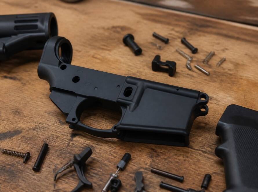
Essential tools include a small hammer or mallet, precision screwdrivers (both Phillips and flathead), a Dremel tool or similar rotary device with sanding bits, and fine-grit sandpaper (220-320 grit). You’ll also need a small flashlight or headlamp to inspect internal components, a soft cloth for cleaning, and a work surface that allows you to secure your lower receiver safely. Many builders use a padded vise or receiver block to hold the lower during work.
For the super safety kit itself, verify compatibility with your specific lower receiver platform before starting. Polymer Pew offers tested super safety kits designed for precision fit, reducing the likelihood of binding during installation. Check that all components are included: the safety selector lever, detent spring, detent ball, and any timing adjustment shims specific to your kit.
Documentation is critical. Have the manufacturer’s installation guide available, along with reference photos of the assembly. Understanding the bolt carrier group clearance requirements and how the safety mechanism interacts with the trigger assembly prevents costly mistakes during installation.
How to Install Super Safety Without Binding
The installation process requires methodical attention to component alignment and tolerance management. Binding typically occurs when the safety lever contacts the receiver shelf or when the bolt carrier group encounters the safety selector during cycling.
Step 1: Prepare Your Lower Receiver and Components
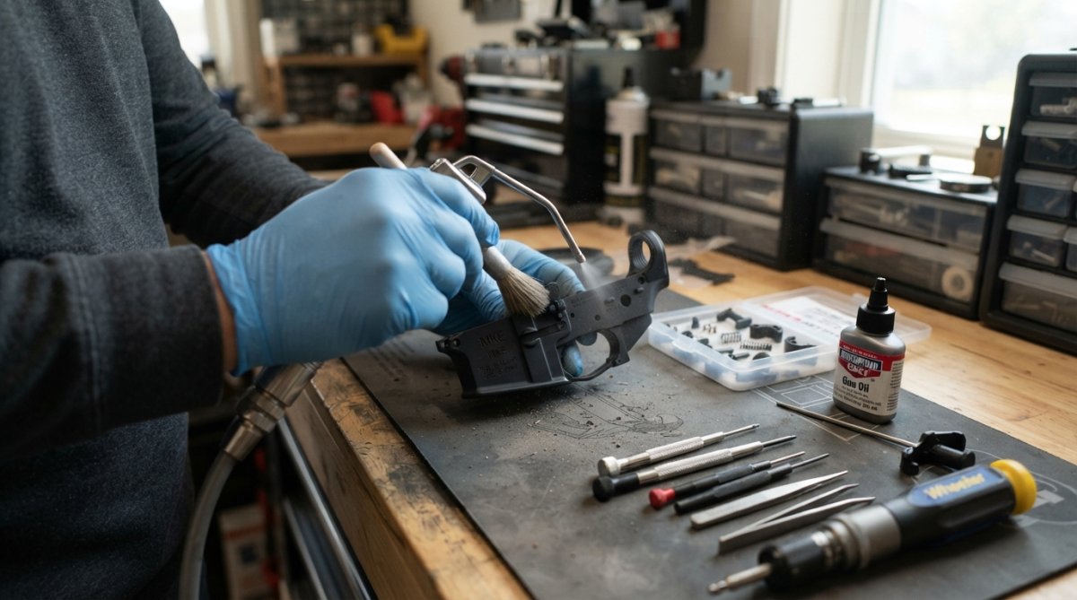
Start by thoroughly cleaning your lower receiver, especially the fire control group pocket and receiver shelf area where the safety selector mounts. Use a soft brush and compressed air to remove any dirt, debris, or manufacturing residue that could interfere with component fit.
Inspect the receiver shelf visually for high spots or burrs. The shelf is the surface against which the safety selector lever rotates, and even minor imperfections can cause binding. If you notice any raised areas, use fine-grit sandpaper to gently smooth them. Work in light passes, you’re removing micro-imperfections, not reshaping the shelf.
Lay out all super safety kit components on a clean surface and verify each piece matches your documentation. Check that the safety lever rotates freely by hand before installation. If it feels stiff or catches, inspect the lever and detent areas for manufacturing defects or debris.
Step 2: Install the Trigger Assembly and Safety Selector
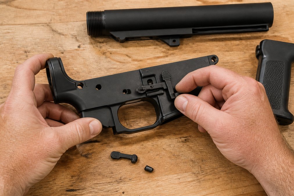
Install your trigger assembly first, as it provides the reference point for safety selector alignment. Follow your specific platform’s trigger installation procedure, ensuring the hammer spring and trigger spring are properly seated.
Once the trigger assembly is in place, install the detent ball and spring into the safety selector pocket. Position the safety lever carefully, aligning the detent ball hole with the spring. This is where many binding issues originate, if the detent spring tension is too high or the ball isn’t properly seated, the lever won’t rotate smoothly.
Insert the safety selector lever slowly and deliberately. You should feel consistent resistance from the detent spring, not sudden catches or binding points. Rotate the lever through its full range of motion (typically from fire to safe and back) at least five times. The rotation should be smooth and require moderate, consistent pressure, not easy (which indicates insufficient detent tension) or difficult (which indicates binding).
If you feel binding during rotation, remove the lever and inspect the detent ball and spring assembly. Ensure the ball is fully seated in its pocket and the spring provides even pressure. Sometimes a slight adjustment to spring positioning eliminates binding before it becomes a problem.
Step 3: Check Bolt Carrier Group Clearance
This step prevents the most common binding issue: contact between the bolt carrier group and the safety selector lever during manual cycling. The bolt carrier group must have adequate clearance to move freely without contacting the safety mechanism.
Manually cycle your platform (without firing) and observe the bolt carrier group movement. Watch how the bolt carrier group travels in relation to the safety lever. There should be visible daylight between the lever and the bolt carrier group throughout the entire cycling motion.
If the bolt carrier group appears to contact or come very close to the safety lever, you’ll need to modify the receiver shelf. This is where precision tooling becomes essential. Using a Dremel with a small sanding drum or grinding bit, carefully remove material from the shelf in the area where contact occurs. Work in very small increments, removing 0.5mm at a time and testing between each pass.
The goal is to create adequate clearance without compromising structural integrity. Most builders target a minimum of 1.5mm to 2mm of clearance between the bolt carrier group and safety lever at the closest point during cycling. Use your flashlight to inspect this clearance regularly as you work.
Step 4: Test Lever Rotation and Manual Cycling
Once all components are installed, perform comprehensive manual cycling tests. Slowly cycle the action from locked to unlocked position multiple times, feeling for any resistance changes or binding points.
Pay attention to where resistance occurs during the cycling motion. If binding happens at a specific point in the cycle, it indicates contact at that particular angle. This diagnostic information tells you exactly where material removal or adjustment is needed.
Perform at least 20-30 manual cycles before proceeding to dry-fire testing. This extended testing reveals issues that might not appear in a few quick cycles. Many binding problems show up only after repeated use when tolerance stack-up becomes apparent.
How to Prevent Binding in Super Safety Kits
Understanding what causes binding helps you avoid it during installation. Binding occurs at the interface between three key components: the receiver shelf, the safety selector lever, and the bolt carrier group. Any misalignment or manufacturing tolerance stack-up at these interfaces creates friction and resistance.
The receiver shelf is the primary culprit in most binding scenarios. If the shelf has a high spot directly in the path of the safety lever, or if it’s not perfectly flat, the lever will catch as it rotates. Similarly, if the bolt carrier group has insufficient clearance from the safety selector, cycling will cause contact and binding.
Component compatibility matters significantly. Different lower receiver manufacturers have slightly different receiver shelf geometry and bolt carrier group dimensions. A super safety kit designed for one platform may have clearance issues on another platform without modification. This is why testing with your specific components is essential.
Detent spring tension affects binding perception. If the detent spring is too tight, the lever requires excessive force to rotate, which feels like binding even if there’s no actual mechanical contact. Conversely, insufficient spring tension makes the lever feel loose and may allow it to shift during cycling, creating contact points.
Polymer Pew’s tested super safety kits are engineered to minimize these issues through precision manufacturing and component selection. However, even with quality components, proper installation technique prevents binding. The installation process itself, how you align components and manage tolerances, determines whether binding occurs.
Super Safety Timing Adjustment for Smooth Function
Timing refers to the relationship between the safety selector lever position and the hammer/trigger assembly state. Proper timing ensures the safety mechanism engages and disengages at the correct points in the cycling sequence, preventing binding and ensuring reliable function.
Most super safety kits include timing adjustment shims or have adjustment mechanisms built into the design. These allow you to fine-tune when the safety selector contacts the hammer or trigger to prevent premature engagement or delayed disengagement.
To check timing, manually cycle your platform while observing the safety lever position relative to hammer position. The safety should engage (block hammer movement) when the lever is in the safe position, and disengage completely when the lever is in the fire position. If the safety engages before the lever reaches the safe position, or if it remains partially engaged in the fire position, timing adjustment is needed.
Consult your specific kit’s documentation for timing adjustment procedures. Some designs use shims placed between the safety selector and receiver, while others use lever positioning adjustments. Make small adjustments and test thoroughly between each change. Timing issues often manifest as binding during specific points in the cycling motion, so careful observation during manual cycling reveals whether adjustment helped.
Super Safety Installation Troubleshooting
Even with careful installation, issues sometimes arise. Understanding common problems and their solutions prevents frustration and ensures reliable function.
Binding During Lever Rotation
If the safety lever binds during rotation, first verify that all components are fully seated. Remove the lever and reinstall it, ensuring the detent ball and spring are properly positioned. Sometimes a component shifts slightly during installation, creating binding that’s easily resolved by reinstalling.
Next, inspect the receiver shelf for high spots using your flashlight. Look for shiny areas where the lever contacts the shelf, these indicate pressure points. If you see such marks, use fine-grit sandpaper to gently smooth the shelf in that area. Work carefully and test frequently to avoid removing too much material.
If binding persists after shelf smoothing, check the safety lever itself for bending or deformation. A bent lever won’t rotate smoothly regardless of receiver condition. Compare your lever to reference photos or another known-good lever if possible. If the lever is bent, replacement is the only solution.
Safety Selector Won’t Lock in Position
If the safety selector won’t stay in the fire or safe position, the detent spring or ball is likely problematic. Remove the lever and inspect the detent components. The spring should have consistent tension, and the ball should be smooth and undamaged.
Sometimes the detent pocket in the receiver is slightly shallow, preventing the ball from fully seating. If this is the case, you can carefully deepen the pocket using a small punch and hammer, striking very gently to avoid damaging the receiver. This is precision work, strike only hard enough to move the ball deeper into the pocket.
Alternatively, some builders use slightly larger detent balls (0.250" instead of 0.245") to increase engagement. This requires filing or grinding the detent pocket slightly larger, but provides more positive locking. This adjustment should only be attempted if you’re comfortable with precision metalworking.
Hammer or Trigger Not Resetting Properly
If the hammer or trigger fails to reset after firing, the issue usually involves spring tension or component binding. First, verify that all springs are fully seated and undamaged. A weak or damaged hammer spring won’t reset the hammer reliably.
Check that the trigger assembly isn’t contacting the safety selector during reset. This contact prevents the trigger from moving freely. If contact is occurring, you may need to adjust the trigger assembly position slightly or remove additional material from the receiver shelf in the trigger area.
Dry-Fire Testing and Function Verification
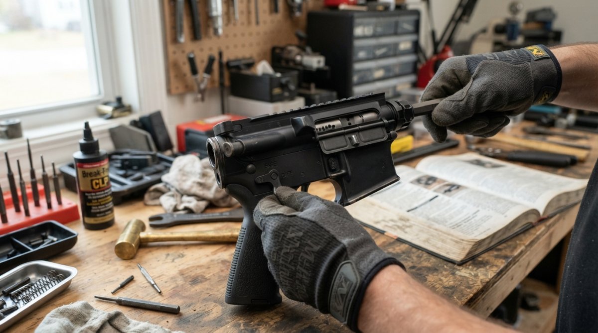
After installation and troubleshooting, comprehensive dry-fire testing confirms everything works correctly. Dry-fire testing means cycling the action without ammunition present, allowing you to safely verify function.
Begin with 50 manual dry-fire cycles, alternating between safe and fire positions. Feel for any binding, resistance changes, or unusual sounds. The action should cycle smoothly with consistent resistance throughout.
Next, perform trigger reset tests. In the fire position, press the trigger and release it, observing whether the trigger resets fully. Repeat this 20 times. The trigger should reset consistently without any hesitation or incomplete reset.
Test the safety mechanism’s actual function by engaging the safety while the hammer is in the cocked position. The hammer should not fall when the safety is engaged. Press the trigger while the safety is engaged, there should be no movement at all. This confirms the safety is blocking trigger and hammer movement correctly.
Finally, perform rapid cycling tests. Quickly cycle the action 30-40 times in succession, switching between safe and fire positions. This extended testing reveals any issues that might not appear during slow, deliberate testing. Rapid cycling can expose tolerance stack-up problems or friction points that only become apparent under more demanding use.
If any issues appear during dry-fire testing, return to the relevant troubleshooting section and address the specific problem. Once dry-fire testing is complete with no issues, your super safety installation is complete and the platform is ready for live-fire testing at an appropriate range.
Installing a super safety without binding requires patience, precision, and attention to the specific interfaces where binding occurs. The receiver shelf, safety selector lever, and bolt carrier group clearance are the critical focus areas. Polymer Pew’s super safety kits are engineered for compatibility and precision fit, but proper installation technique, careful component alignment, tolerance management, and thorough testing, determines whether binding issues develop.
The process isn’t complicated, but it demands methodical work. Test frequently between each step, make small adjustments rather than large ones, and document what you find during testing. This approach prevents costly mistakes and ensures reliable function. Whether you’re building a clone platform or upgrading an existing system, following these installation procedures and troubleshooting guidance helps you achieve smooth, reliable operation without the binding issues that plague poor installations. Get your super safety kit from Polymer Pew and follow this guide to ensure your custom build performs flawlessly.
Frequently Asked Questions
What causes binding in a super safety mechanism?
Binding typically occurs when the receiver shelf hasn't been properly modified or when the bolt carrier group contacts the safety lever during rotation. Insufficient clearance between components, tight spring tension, or misalignment of the trigger assembly can create friction points. Material burrs from drilling or milling, inadequate sanding of contact surfaces, and incorrect timing of the safety cam all contribute to binding. Proper tolerance management and careful shelf modification prevent most binding issues.
How do I prevent binding in super safety kits during installation?
Start by verifying receiver shelf compatibility and smoothing all contact points with fine-grit sandpaper or a Dremel tool. Ensure the bolt carrier group has adequate clearance by manually cycling the action before final assembly. Check that spring tension isn't excessive, as this increases friction at contact points. Install anti-walk pins to maintain alignment of the trigger assembly. Test lever rotation throughout the full range of motion in all three positions (safe, semi, fire) before installing the upper receiver. Gradual, deliberate testing catches binding early.
Do I need a full auto BCG for a super safety kit?
No. A standard semi-auto bolt carrier group works with most super safety kits designed for civilian platforms. However, verify compatibility with your specific kit and lower receiver type, as some configurations may have clearance requirements. The key is ensuring your BCG has proper clearance with the safety lever and cam during cycling. Check the manufacturer's specifications for your kit to confirm compatibility before purchase.
Is a super safety hard to install?
Installation difficulty depends on your experience level and the quality of your kit. A well-engineered drop-in kit from a reputable manufacturer can be installed in 30-45 minutes with basic tools. The main challenges are achieving proper receiver shelf modification, ensuring adequate clearance, and testing for binding. If you're new to firearm builds, take your time with each step and test frequently. Most binding issues stem from rushing the process or skipping the clearance verification steps, not from the installation itself being inherently difficult.
This article was written using GrandRanker