Table of Contents
- What You Need Before Installing Your MKE Lower Receiver
- Safety Precautions and Workspace Setup
- MKE AP5 Lower Receiver: Compatibility and Mil-Spec Nuances
- Lower Parts Kit Installation: Magazine Catch, Bolt Catch, and Trigger Guard
- Fire Control Group Installation: Trigger, Hammer, and Safety Selector
- Pistol Grip and Buffer Tube Installation on Your MKE Lower Receiver
- Visual Troubleshooting: Common Mistakes and Fitment Issues
- Function Test and Final Safety Check
Last Updated: August 2, 2026
Getting the lower parts kit installed correctly is where most first-time AR-style builds either succeed or stall. If you’re searching for how to install mke lower receiver components step by step, this guide from Polymer Pew covers every stage of the process, from tools and workspace prep through the final function test. The MKE AP5 lower receiver has specific compatibility nuances that generic AR guides skip entirely, and those gaps are exactly where builds go wrong. Below, we’ll walk through every sub-assembly in sequence, flag the mistakes that cause the most headaches, and give you the kind of insider detail that turns a frustrating first build into a clean, reliable platform.
What You Need Before Installing Your MKE Lower Receiver
Total Time: 2-3 hours
Difficulty: Intermediate
Required Tools and Equipment
The core toolkit for a lower parts kit installation is not exotic, but every item on this list earns its place:
- Bench block (polymer or steel, with through-holes for roll pin support)
- Punch set: 1/8", 3/32", and 5/32" roll pin punches plus a starter punch
- Hammer (12-16 oz nylon or brass-faced)
- Hex key set (metric and standard, 1/16" through 3/8")
- Torque wrench capable of reaching 40-80 ft-lbs for the castle nut
- Castle nut wrench
- Needle-nose pliers
- Small flathead screwdriver
- Armorer’s block or lower receiver vise block
- Blue Loctite (for set screws)
- Needle-tipped oil bottle for lubrication
Tool-Specific Alternatives for Budget Builders
You don’t need a dedicated armorer’s block on day one. A folded shop towel over a sturdy bench block works for most pin installations. For the castle nut, a quality adjustable wrench with a length of steel pipe for torque use gets you to spec if you don’t own a dedicated wrench yet. The one thing you should not substitute is the punch set, a proper roll pin punch with a cup tip costs under $20 and saves you from a ruined build.
According to ATF’s guidance on firearm assembly and compliance, builders should verify that all components comply with applicable federal and state regulations before beginning any assembly.
A roll pin holder tool lets you seat roll pins by hand before driving them with a punch. For the trigger guard roll pin in particular, this prevents the single most common lower receiver scratch.
Safety Precautions and Workspace Setup
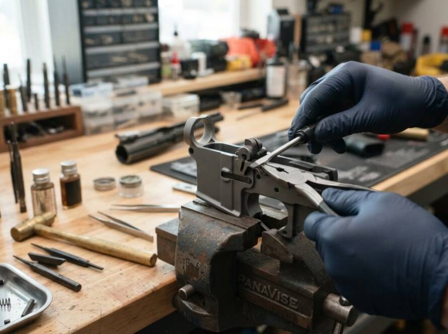
Clear the workspace before anything else. Verify the receiver is unloaded, then verify it again. Small detent springs and roll pins are the most common parts to lose during a lower receiver build, and they move fast on a cluttered bench.
Set up your workspace with these priorities:
- Work over a light-colored surface (white sheet or butcher paper) so springs are visible if they launch
- Ensure adequate lighting, especially for sear engagement components
- Keep a parts tray or magnetic mat within arm’s reach
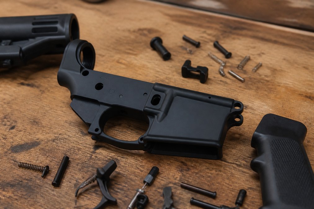
- Have the lower parts kit laid out in assembly sequence before starting
The most dangerous moment in any build is distraction. Detent springs under tension will eject if you lose control of the assembly.
Never drive a roll pin without a bench block supporting the receiver. Unsupported receiver walls can crack under punch pressure, especially on aluminum lower receivers. Cracked receivers are not repairable and represent a total loss.
MKE AP5 Lower Receiver: Compatibility and Mil-Spec Nuances
The MKE AP5 lower receiver is not a standard AR-15 mil-spec lower. The AP5 platform is HK MP5-pattern, which means the receiver extension, buffer tube, and fire control group dimensions differ from a standard AR build.
Key compatibility points to verify before starting your build:
- The AP5 lower uses an HK-pattern fire control group, not a standard AR trigger group
- Buffer tube threads on the AP5 are metric, not the standard AR 1-5/8" x 24 TPI
- Magazine catch geometry is specific to MP5-pattern magazines
- Safety selector detents and spring tension specs differ from mil-spec AR dimensions
If you’re running Polymer Pew’s aluminum full-size MKE lower receivers, these have been tested for variant compatibility across common AP5 clones, which eliminates the fitment guesswork that plagues generic aftermarket options. For builders sourcing components across multiple suppliers, always cross-reference the receiver’s fire control group pocket dimensions before purchasing a trigger or disconnector.
Lower Parts Kit Installation: Magazine Catch, Bolt Catch, and Trigger Guard
The lower parts kit installation follows a logical sequence: work from the simplest sub-assemblies to the most complex.
Installing the Magazine Catch and Magazine Release Button
The magazine catch assembly consists of three parts: the magazine catch body, the magazine release button, and the magazine catch spring.
- Insert the magazine catch through the left side of the receiver
- Thread the magazine catch spring onto the right-side post
- Thread the magazine release button onto the post, compressing the spring
- Hold the button depressed and rotate the magazine catch body clockwise until it’s flush or slightly recessed from the receiver face
Over-threading the magazine release button causes the magazine to drop inconsistently or not lock at all. Test by inserting an empty magazine and verifying positive lock and clean release.
Bolt Catch and Roll Pin Installation
The bolt catch uses a roll pin to pivot on the receiver.
- Place the bolt catch spring and plunger into the bolt catch pocket
- Hold the bolt catch in position while compressing the spring
- Start the roll pin by hand or with a roll pin holder
- Drive the roll pin through with a 1/8" roll pin punch, supporting the receiver on a bench block
The roll pin must be centered (flush or slightly below the receiver surface on both sides). A roll pin punch with a cup tip prevents the punch from slipping off the pin head mid-drive.
Trigger Guard Installation
Trigger guard installation involves one roll pin at the rear and a detent at the front.
- Seat the front trigger guard tab into the receiver’s front detent notch
- Align the rear trigger guard hole with the receiver hole
- Drive the roll pin through using a 1/8" punch with the receiver supported on a bench block
Apply firm, controlled hammer strikes.
Fire Control Group Installation: Trigger, Hammer, and Safety Selector
The fire control group is the heart of the build, and the sequence here matters more than anywhere else in the assembly.
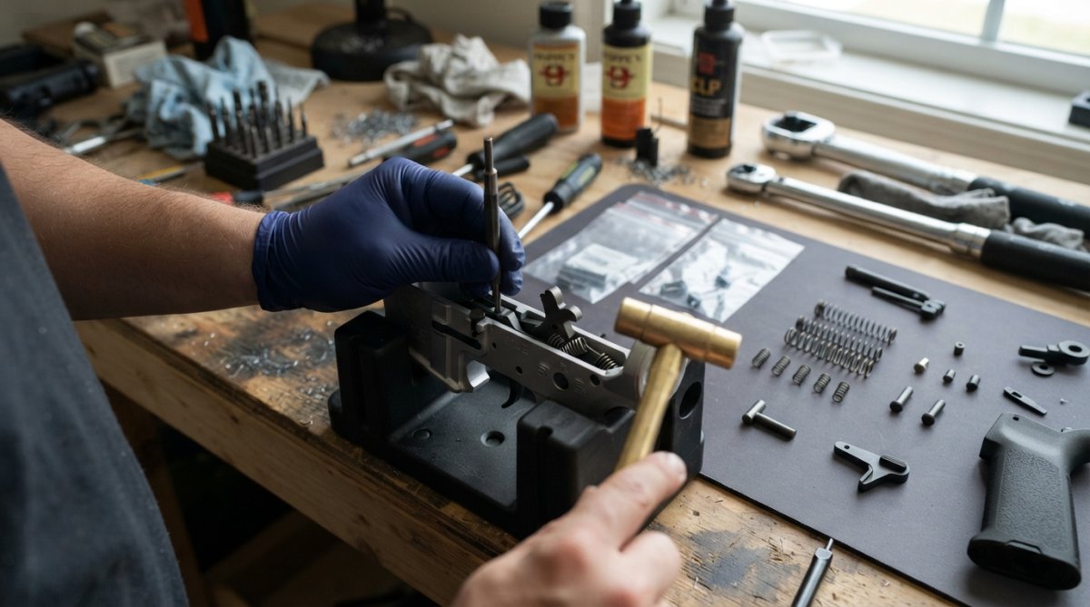
Trigger and Disconnector Assembly
The trigger and disconnector assembly determines sear engagement quality and reset feel. Assemble this before installing it in the receiver.
- Place the disconnector spring into the disconnector pocket (small end down)
- Seat the disconnector onto the trigger body, aligning the holes
- Verify the disconnector rotates freely under spring tension before proceeding
Install the trigger assembly into the fire control group pocket with the trigger spring legs straddling the bottom of the pocket. Press the trigger pin through from left to right with firm but consistent pressure. If the pin binds, verify the trigger spring legs are correctly positioned and not caught on the receiver walls.
Before pressing the trigger pin fully home, do a quick visual check that the disconnector is seated correctly and the spring is not kinked.
Hammer Spring and Hammer Pin Installation
The hammer spring installation is where spring tension management becomes critical.
- Place the hammer spring onto the hammer with the legs facing forward (toward the muzzle end of the receiver)
- Cock the hammer back and compress the spring legs around the trigger pin
- Align the hammer hole with the receiver holes and drive the hammer pin from left to right
The hammer spring legs must wrap around the trigger pin, not sit above or below it. Incorrect spring orientation is the leading cause of light primer strikes and failure-to-fire issues. After installing the hammer pin, manually cock the hammer and release it. The hammer should fall crisply with no drag or binding.
Safety Selector Installation and Detent Spring Alignment
Safety selector installation requires the pistol grip to be partially staged because the detent spring seats inside the grip screw hole.
- Insert the safety selector from the left side of the receiver
- Drop the safety selector detent into the detent hole on the right side of the receiver
- Place the detent spring on top of the detent
- Hold the spring in place while threading the pistol grip screw up through the grip, capturing the spring
A small piece of masking tape over the detent hole temporarily holds the spring in position while you seat the grip.
Pistol Grip and Buffer Tube Installation on Your MKE Lower Receiver
With the fire control group installed, the pistol grip and buffer tube assembly complete the lower receiver build.
Pistol Grip Installation
- Verify the safety selector detent and spring are in position
- Seat the pistol grip over the receiver, aligning the grip screw hole with the detent spring
- Thread the grip screw through the grip into the receiver
- Torque the grip screw to spec (typically 45-55 in-lbs) using a hex key
Over-torquing the grip screw cracks polymer grips and strips the receiver threads. Snug plus a quarter-turn is a reliable field approach if you don’t have an inch-pound torque wrench handy.
Buffer Tube, End Plate, Castle Nut, and Buffer Retainer Assembly
The buffer tube assembly sequence is: end plate, castle nut, then receiver extension (buffer tube), with the buffer retainer and detent installed before the tube is fully threaded home.
- Thread the castle nut onto the receiver extension several turns
- Slide the end plate over the receiver extension, behind the castle nut
- Thread the receiver extension into the lower receiver until the buffer retainer hole is visible
- Insert the buffer retainer and buffer retainer spring into the receiver hole
- Continue threading the receiver extension until it captures the buffer retainer
- Slide the end plate forward against the receiver
- Torque the castle nut to 40-80 ft-lbs using a castle nut wrench
- Stake the castle nut with a punch to prevent rotation
The end plate must capture the sling loop (if present) before the castle nut is tightened.
According to SAAMI technical standards for firearm assembly torque specifications, proper torque application on receiver extension hardware is critical to maintaining structural integrity and function under firing loads.
Visual Troubleshooting: Common Mistakes and Fitment Issues
Most build problems fall into a small number of categories. Here’s a quick-reference guide to the issues builders encounter most often during a lower receiver build:
| Problem | Likely Cause | Fix |
|---|---|---|
| Magazine won’t lock in | Magazine catch over-threaded | Back out magazine release button one turn |
| Hammer follows bolt carrier | Disconnector spring inverted or missing | Disassemble FCG, verify disconnector spring orientation |
| Safety selector won’t rotate | Detent spring not seated in grip | Remove grip, reseat detent and spring |
| Buffer tube wobbles | Castle nut under-torqued | Re-torque to 40-80 ft-lbs, re-stake |
| Trigger pin walks out | No roll pin or anti-walk pin installed | Install trigger pin anti-walk kit |
| Roll pin proud of receiver | Punch slipped, pin not fully seated | Re-drive with proper roll pin punch |
| Takedown pin binds | Takedown detent spring not compressed | Verify detent and spring are fully seated |
The disconnector issue is the one that gets missed most often because the trigger still functions during dry-fire testing. The failure only appears under live fire when the disconnector fails to catch the hammer on reset.
If the safety selector passes through the “fire” position with no detent feel, the safety selector detent or spring is missing. Do not function test or fire the weapon until this is corrected. A missing detent allows the safety to rotate into an undefined position under recoil.
Standard mil-spec lower parts kits may not include the correct trigger pin diameter or safety selector detent geometry for AP5-pattern receivers. Always verify your lower parts kit is specified for the MKE platform before installation. Polymer Pew’s specialized super safety kits are designed with this compatibility requirement in mind, which can provide a cleaner fit for AP5 builds than generic mil-spec kits.
Function Test and Final Safety Check
A proper function test verifies every sub-assembly before the lower is mated to an upper.
Function test sequence:
- Verify the safety selector moves positively between safe and fire positions with clear detent feel at each position
- With the selector on "safe," pull the trigger. The hammer must not fall.
- Move the selector to "fire," cock the hammer, and pull the trigger. The hammer should fall.
- Hold the trigger rearward, cock the hammer again, and slowly release the trigger. You should feel and hear the disconnector reset before the trigger reaches its forward position.
- With the hammer cocked, press the bolt catch. Verify it holds the hammer back.
- Test the magazine catch with an empty magazine. Positive lock, clean release.
- Test the takedown pin and pivot pin. Both should move freely with light thumb pressure.
The disconnector reset check in step 4 is critical. If the hammer follows the bolt carrier during live fire, this test would have caught it.
As documented in NSSF’s guide to safe firearm handling and function testing, verifying all safety mechanisms function correctly before live fire is a fundamental responsibility for any builder or owner.
A build that passes this function test is ready for upper receiver mating and a range session. If any step fails, trace it back to the relevant sub-assembly using the troubleshooting table above before proceeding.
Frequently Asked Questions
What tools do I need to install an MKE lower receiver?
A solid MKE lower receiver build requires a punch set (including a roll pin punch), a bench block, a hex key set, a castle nut wrench, and a torque wrench for the receiver extension nut. A pivot pin and takedown pin installation tool makes detent spring work much less frustrating. For budget builders, a sturdy vise with polymer jaw blocks and a standard armorer's block can substitute for several specialty fixtures without sacrificing accuracy.
Is the MKE AP5 lower receiver compatible with standard mil-spec lower parts kits?
The MKE AP5 lower receiver is designed around the HK33/MP5 platform, so it does not accept standard AR-15 mil-spec lower parts kits. Fire control group components, the safety selector, trigger pin, hammer pin, and pistol grip dimensions differ from AR-pattern receivers. Always confirm you are sourcing an MKE-specific lower parts kit and compatible buffer tube or receiver extension setup before purchasing parts to avoid fitment issues.
How do I troubleshoot binding issues with the safety selector or trigger after installation?
Binding in the safety selector usually points to a misaligned detent spring or a detent that was not fully seated before the pistol grip was torqued down. Remove the grip, reset the detent and spring, and reinstall. Trigger binding after fire control group installation often means the disconnector spring is flipped or the trigger pin is not fully seated. A bench block and the right punch size will help you drive pins straight without damaging the receiver.
What is the correct torque for the castle nut on an MKE lower receiver buffer tube assembly?
Mil-spec castle nut torque specifications typically fall between 35 and 40 ft-lbs, though always verify against the manufacturer's documentation for your specific receiver extension and end plate. Under-torquing leaves the castle nut loose under recoil; over-torquing can crack the receiver threads. After reaching proper torque, stake the castle nut to the end plate at two or more points to prevent it from backing off during use.
Can a first-time builder successfully install an MKE lower receiver without gunsmithing experience?
Yes, with patience and the right tools. The most common stumbling blocks for first-timers are the roll pin for the bolt catch (use a roll pin punch and bench block), the takedown detent and pivot detent springs (a detent installation tool saves a lot of lost springs), and the castle nut torque on the buffer tube. Work slowly, follow each step in sequence, and perform a full function test before considering the build complete.
Building on an MKE platform requires more precision than a standard mil-spec AR build, and generic guides leave too many compatibility gaps unaddressed. Polymer Pew’s aluminum full-size MKE lower receivers are tested for variant compatibility, and the specialized super safety kits and flat triggers are engineered to drop in without the binding issues that plague off-spec aftermarket components. Get your Flatties here and build with hardware that’s actually designed for the platform.
This article was written using GrandRanker