Table of Contents
- What You’ll Need Before You Start
- How to Diagnose Super Safety Binding Before It Kills Reliability
- Upper Receiver Shelf and Cam Clearance: The Most Common Culprits
- Super Safety Centering Block Benefits and Lateral Wobble Fixes
- Shim Installation, Polishing, and Contact Point Refinement
- Super Safety Installation Troubleshooting: Trip Bar, Timing, and BCG Cycling
- Super Safety Dead Trigger Fix: Causes and Corrections
- Material-Specific Wear Patterns and Lubrication Best Practices
Last Updated: August 3, 2026
Binding in a super safety kit almost always comes down to clearance, alignment, or a missed contact point during installation. If you’ve dry-cycled the action twice and still feel grinding resistance, this guide walks through every common failure mode and provides specific fixes. Binding is a symptom with at least six distinct causes, each demanding a different solution.
What You’ll Need Before You Start
Gather the right tools before touching anything. Attempting troubleshooting without proper equipment leads to over-removal, which is permanent and expensive.
Tools and materials:
- Calipers or feeler gauge set
- 220, 400, and 600-grit wet/dry sandpaper
- Dremel rotary tool with felt polishing wheel and fine carbide bit
- Needle files (flat and half-round)
- Function check dummy round or snap caps
- Graduated shims
- Blue threadlocker
- Firearm-specific lubricant
- Clean gunsmithing mat and good lighting
Run a function check before starting to establish a baseline. If the trigger resets but drags, that’s different from a dead trigger that won’t reset at all.
Use a marker to coat contact surfaces before assembly. Wear marks show exactly where friction occurs, not where you think it is.
How to Diagnose Super Safety Binding Before It Kills Reliability
Never remove material until you’ve confirmed the exact contact point.
Identifying Binding Symptoms vs. Normal Resistance
Binding symptoms fall into three categories:
- Rotational drag – The safety selector moves but requires excessive force, typically pointing to lever or cam interference with the receiver shelf or lower receiver walls.
- Dead trigger after selector engagement – The trigger does not move when the safety rotates to fire, usually a timing issue involving the trip bar or cam geometry.
- Lateral wobble with intermittent function – The safety rocks side-to-side with inconsistent function, pointing to insufficient centering or shim thickness.
Normal resistance feels like a firm, positive detent click. Binding feels like grinding, sticking mid-rotation, or a trigger that goes dead after the selector moves.
Visual Diagnostic Flowchart: Where Is the Friction Coming From?
Work through this sequence before picking up any abrasive:
- Remove the super safety assembly from the lower.
- Inspect the lever and cam surfaces for bright wear marks or burrs.
- Check the upper receiver shelf contact area for high spots.
- Verify shim thickness against your specific lower’s spec.
- Confirm the trip bar is correctly oriented and seated.
- Cycle the bolt carrier group manually and observe timing at the trip bar.
According to ATF guidelines on firearm component modifications, any modification to fire-control components must preserve the original safety function.
| Symptom | Most Likely Cause | First Fix to Try |
|---|---|---|
| Selector drags mid-rotation | Upper receiver shelf contact | Polish shelf, check cam clearance |
| Dead trigger at fire position | Trip bar misalignment or timing | Check trip bar orientation and BCG timing |
| Lateral wobble | Insufficient shim or no centering block | Add shim, install centering block |
| Binding only under recoil | Tolerance stacking under load | Full disassembly, lube all contact points |
| Gritty rotation, no dead trigger | Rough cam or lever surface | Polish cam and lever with 600-grit |
Upper Receiver Shelf and Cam Clearance: The Most Common Culprits
Most binding cases trace back here. The upper receiver shelf is the ledge inside the lower receiver where the cam rotates. Even a few thousandths of an inch of interference creates significant drag.
Upper Receiver Shelf Modification Step-by-Step
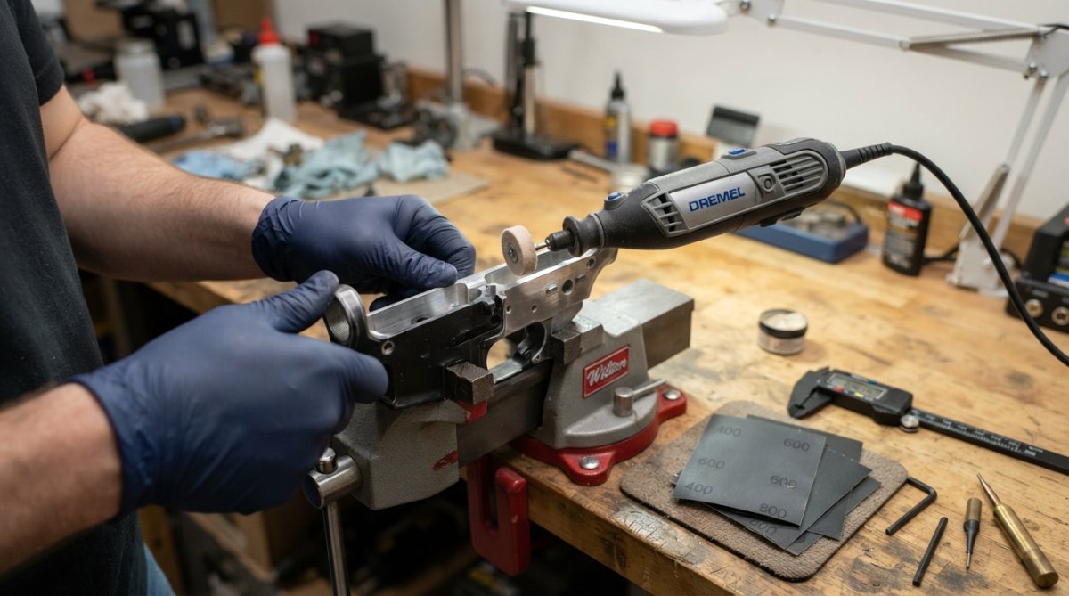
- Identify the contact point using the marker method. The bright spot on the shelf is your target.
- Start with 400-grit sandpaper wrapped around a flat backing block. Do not use a Dremel freehand unless experienced. Freehand removal creates uneven surfaces that cause new contact points.
- Make five strokes, then test-fit. Repeat. Goal is clearance of roughly 0.005 to 0.010 inches between the cam and shelf at full rotation.
- Finish with 600-grit to reduce surface friction.
- Run a function check with snap caps before reassembly.
Never use coarse bits (below 220-grit equivalent) on the receiver shelf. Removing too much material creates a cam that flops through its rotation arc with no positive stop, which is a safety failure.
Lever and Cam Clearance Adjustments
The lever rides alongside the cam and can bind against receiver walls if geometry is off. Check lever clearance by rotating the selector slowly and feeling for resistance at specific positions. Binding at 45 degrees typically means the lever contacts the receiver wall. Binding at 90 degrees usually means the cam hits the shelf.
For lever clearance, use a needle file on the lever edges rather than the receiver. The lever is replaceable; the receiver is not. Remove material in small passes, deburr with 600-grit, and test-fit after each pass.
Super Safety Centering Block Benefits and Lateral Wobble Fixes
Lateral wobble is underdiagnosed. A super safety that rocks side-to-side creates inconsistent contact geometry on every cycle, producing intermittent function rather than consistent binding.
The super safety centering block constrains lateral play by positioning the safety assembly precisely on the receiver’s centerline. A correctly centered assembly ensures the trip bar engages the bolt carrier group at the same point on every cycle, which is the foundation of consistent mechanical timing.
Fixing lateral wobble:
- Measure the gap between the safety assembly and receiver wall using feeler gauges.
- Select a shim thickness that closes the gap to near-zero without creating binding.
- Install the centering block according to your kit’s specification.
- Verify the assembly rotates freely with no side-to-side movement.
A centering block alone does not compensate for a shim that’s too thin. The two work together.
Shim Installation, Polishing, and Contact Point Refinement
Shim selection is where many builders make a binary mistake: they either skip shims or install the thickest available shim and hope for the best.
Proper Shim Installation Techniques
Shims control the axial position of the safety assembly within the lower receiver. Too thin, and you get lateral play. Too thick, and you introduce binding at the cam-to-shelf interface.
The correct approach:
- Start with the thinnest available shim.
- Assemble the safety kit fully and test rotation.
- Check for lateral play using the feeler gauge.
- Add shim thickness incrementally until play is eliminated without adding rotational resistance.
- Once correct thickness is identified, apply a small amount of blue threadlocker to the shim seat if the kit design permits it.
Sandpaper Grit Recommendations and Dremel Polishing
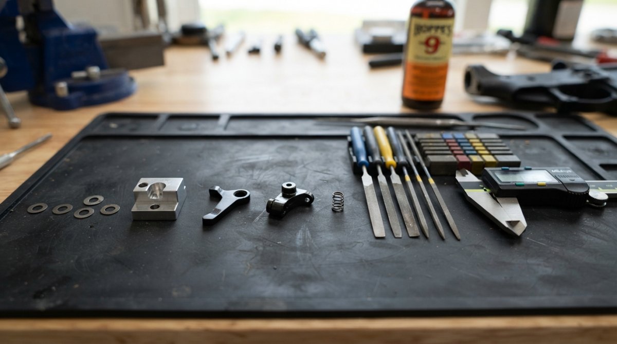
Recommended grit progression:
- 220-grit: Use only on heavily burred surfaces or obvious high spots. Not for receiver shelves.
- 400-grit: Standard starting point for cam and lever polishing. Removes minor burrs and machining marks.
- 600-grit: Finishing pass on all contact surfaces. Dramatically reduces friction without changing geometry.
- Dremel with felt polishing wheel + polishing compound: Final step on cam and lever faces. Creates a near-mirror finish that minimizes friction.
Keep Dremel RPM below 5,000 on aluminum components. High RPM generates heat that can alter material temper and create micro-surface irregularities that increase friction.
According to NIST guidelines on surface finish and friction in mechanical components, surface roughness has a direct relationship to dynamic friction coefficients. A polished surface at Ra 0.4 or better reduces friction significantly compared to a machined surface at Ra 1.6.
After polishing, wipe all surfaces with a clean patch before applying lubricant. Polishing compound residue acts as a mild abrasive during cycling.
Super Safety Installation Troubleshooting: Trip Bar, Timing, and BCG Cycling
The trip bar is the component most often overlooked during installation. It’s small and looks symmetrical, but it cannot be installed in either orientation.
Trip Bar Orientation and Alignment Checks
Trip bar orientation is specific to the kit. Installing it reversed creates a dead trigger at the fire position because the trip bar fails to engage the bolt carrier group at the correct point.
Check orientation by:
- Confirming the trip bar’s engagement face is oriented toward the bolt carrier group travel path.
- Verifying the trip bar sits flush in its seat with no lateral offset.
- Cycling the BCG manually by hand and watching the trip bar engagement. You should see the trip bar rise and fall cleanly as the BCG passes over it.
If the trip bar is correctly oriented but function is inconsistent, the issue is usually alignment. A trip bar offset by even a small amount creates partial engagement, producing intermittent dead trigger.
Bolt Carrier Group Cycling Issues and Tolerance Stacking
Bolt carrier group cycling problems are almost always tolerance stacking issues. Individual components are within spec, but their combined dimensional variation creates interference.
Test the BCG cycling with the safety in the fire position and trigger group installed. If the BCG cycles cleanly by hand but binds under spring tension, the issue is spring rate combined with tolerance stack, not a single component problem.
According to SAAMI standards for firearm component tolerances, acceptable tolerance ranges for fire-control components are wider than many builders expect. Two components individually within spec can still create interference when combined. The fix is selective fitting, not replacement.
For BCG cycling issues:
- Verify the BCG key is properly staked and not adding lateral movement.
- Check that the bolt locking lugs are not creating drag against the upper receiver.
- Confirm the buffer spring rate is appropriate for the platform.
Super Safety Dead Trigger Fix: Causes and Corrections
Identify whether the failure is mechanical or timing-related. These are different problems with different solutions.
Mechanical dead trigger: The trigger does not move at all when the selector is at fire. The cam is blocking the trigger bow, meaning the cam is not fully rotating to the fire position. Check cam-to-shelf clearance first.
Timing dead trigger: The trigger moves but the hammer does not fall, or the hammer falls but the firing pin does not reach the primer. This is a BCG timing issue or disconnector problem unrelated to the super safety kit.
The super safety dead trigger fix sequence:
- Confirm the selector rotates fully to the fire detent position.
- Verify the cam has cleared the trigger bow completely at the fire position.
- Check that the trip bar is engaging the BCG at the correct timing point.
- Test the trigger group independently with the safety removed.
If the trigger functions correctly with the safety removed but produces a dead trigger with the safety installed, the problem is definitively within the super safety assembly.
Material-Specific Wear Patterns and Lubrication Best Practices
Aluminum-on-aluminum contact produces accelerated wear at the cam-to-shelf interface. Anodized aluminum has better wear resistance than bare aluminum, but the anodizing layer is thin. Once worn through, the underlying aluminum wears quickly.
Stainless steel components wear more slowly but create more friction against aluminum receiver surfaces than polymer or phosphate-coated steel. If your kit uses stainless steel internals against an aluminum receiver, prioritize polishing the stainless components.
Preventative maintenance schedule:
| Interval | Action |
|---|---|
| Every 500 rounds | Inspect and lube all safety contact points |
| Every 1,000 rounds | Disassemble and inspect for wear at cam and shelf |
| Every 2,500 rounds | Full polishing refresh on cam and lever faces |
| Annually | Replace shims if lateral play has returned |
Lubrication best practices:
- Apply lubricant to the cam faces, lever edges, and receiver shelf contact area.
- Use a thin film, not a heavy coat. Excess lubricant attracts carbon and debris, accelerating wear.
- Avoid dry lubricants like PTFE-only sprays on high-load contact points. They wear off faster than oil-based lubricants under cycling loads.
- After polishing, clean all surfaces completely before applying fresh lubricant. Polishing compound mixed with lubricant creates a lapping compound that continues removing material.
Prevent binding in super safety kits by working systematically from diagnosis to targeted correction, never removing material speculatively, and maintaining the assembly on a regular schedule.
Binding in a super safety kit is solvable when you approach it with the right components. Polymer Pew’s super safety kits feature anodized aluminum housings and stainless steel internals. Get your Flatties here and skip the guesswork.
Frequently Asked Questions
Why does my super safety bind when the rifle is tilted?
Tilting the rifle shifts the bolt carrier group laterally inside the upper receiver, which increases side-load pressure on the safety lever and cam. If your centering block is worn, missing, or improperly installed, that lateral play has nothing to correct it, and the lever drags against the receiver wall. Check your centering block fit first, then inspect the cam clearance on the upper receiver shelf. Proper shim thickness on both sides of the housing usually resolves tilt-induced binding in super safety kits.
What causes a dead trigger in a super safety setup?
A dead trigger after installing a super safety kit almost always traces back to one of three issues: incorrect trip bar orientation blocking the disconnector, insufficient cam clearance causing the lever to hang up mid-cycle, or a bolt carrier group that isn't cycling far enough rearward to reset the trigger. Run a slow-motion function check by hand-cycling the BCG. If the trigger resets manually but not under live fire, the BCG cycling stroke or gas timing is the culprit, not the safety components themselves.
What is the role of a centering block in preventing super safety binding?
The centering block keeps the super safety housing aligned on the center axis of the lower receiver, eliminating lateral wobble. Without it, the housing can shift left or right under recoil or during selector rotation, causing the lever to contact the receiver walls or the bolt carrier group at an off-angle. A properly fitted centering block distributes side load evenly, reduces friction at the contact points, and maintains consistent mechanical timing across every firing cycle, which is the foundation of reliable function.
Do I need a specific bolt carrier group for a super safety kit?
Most super safety kits are designed to work with standard full-auto or semi-auto BCG profiles, but tolerance stacking matters. A BCG with oversized or out-of-spec dimensions can create interference with the trip bar or cam during the rearward stroke, causing cycling issues that mimic binding. Verify your BCG's overall length and carrier key height are within spec before troubleshooting the safety components themselves. Full-auto BCGs are commonly recommended for super safety builds because their geometry is more predictable at the trip bar contact point.
How do I troubleshoot super safety installation problems at home?
Start with a full disassembly and dry function check before any modification. Rotate the selector through all positions and feel for the exact point of resistance. Check the upper receiver shelf for contact marks left by the cam, inspect the trip bar for correct orientation, and verify shim thickness on both sides of the housing. Use a marker on contact points, reassemble, cycle the action, then disassemble again to see exactly where metal is touching. Address one variable at a time so you can confirm what fixed the super safety binding issue.
This article was written using GrandRanker